MET RC BAJA
Analysis
Multiple analysis will be carried out to ensure specific designs of parts or assemblies will have the ability to pass the tests for the requirements set forth. Different approaches will be used in order accurately complete the analysis. Mechanics of Materials, Statics, Geometry, and Kinematics are just some of the approaches that will be use.
Requirements:
-
The lower control arms must not deflect more than 7.62 millimeters (0.30 inches) when the vehicle is placed under a static 9.1 kg (20 lbs.) load that is placed in the center of the chassis.
-
The front and rear suspension must have 60 mm of suspension travel from bottomed out (coil-over/shock fully loaded) to full droop (unloaded fully extended coil-over/shock).
-
The car must be able to turn 180 degrees (full “U-turn”) within a 1-meter radius circle at 2 meters/second.
-
The vehicle must be able to corner each direction at a speed of 5 M/S without any flipping with full lock steering.
-
The drive tires must sustain traction without slipping from a dead stop to immediate application of 75% throttle.
-
One corner of the suspension (ex. Front right tire) must be able to articulate 35 millimeters off ground level while the other three corners of the car tires maintain contact with the ground.
-
The vehicle must successfully land three consecutive vertical drops from a height of 650 mm.
-
The resting compression for the coil over springs must be less than 45% compressed when the vehicle is fully assembled.
-
The front wheels must withstand a front impact at 2 m/s, 3 consecutive times for each side. A failure will be if there is any loss of directional control.
-
Steering must be even from side to side and not differ more than 5 degrees at full steering lock.
All analysis will be shown below:
Analysis 1: Lower Control Arm Bending Deflection
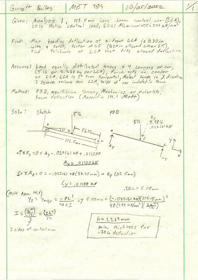
The purpose of Analysis 1 is finding the minimum thickness of the lower control arm that won't allow for more than the maximum deflection requirement.
Figure 2.01
Analysis 2: Steering Angle
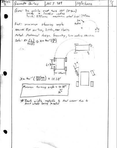
Analysis 2 shows the minimum steering angle needed in order to stay within the maximum turning radius requirement.
Figure 2.02
Analysis 3: Front Suspension Travel

It is a requirement for the RC Baja car to have at least 60 mm of travel and Analysis 3 shows the necessary mounting location of the coil over to allow for at least the required 60mm.
Figure 2.03
Analysis 4: Minimum thickness of Shock Tower Mount
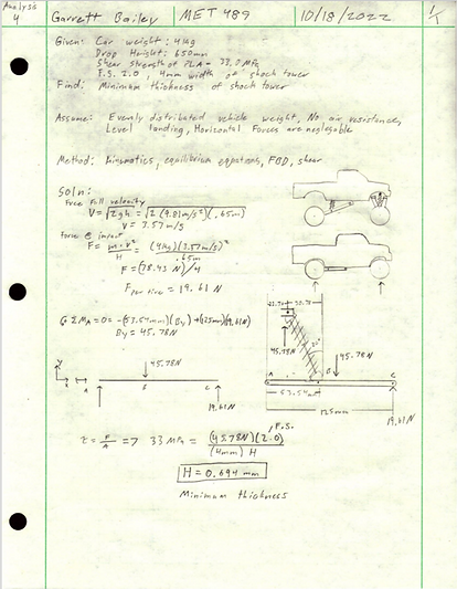
The purpose of Analysis 4 is to find the minimum thickness of the shock tower needed to handle the 650 mm required drop test without breaking.
Figure 2.04
Analysis 5: Minimum Cross Sectional Area of Control Arm (Frontal Impact)

The purpose of Analysis 5 is to find the minimum cross sectional area the control arms need to be to take a 2 m/s front impact directly to the wheel without breaking.
Figure 2.051

Figure 2.052
Analysis 6: Minimum Cross Sectional Area of Trailing Arms

The purpose of Analysis 6 is to find the minimum cross sectional area that the trailing arms need to be so that they won't break with a 650 mm vertical drop test.
Figure 2.06
Analysis 7: Shear Strength of Steering Bolt

For Analysis 7, the focus was on the shear strength of the bolt that connects the tie rod end to the steering knuckle. During the 2 m/s frontal impact, the bolt must not shear.
Figure 2.071

Figure 2.072
Analysis 8: Car Rolling when Turning

According to the project requirements, the RC Baja car must be able to corner with the steering at full lock at a speed of 5 m/s without rolling. Analysis 8 finds the center of gravity height of the car in which allows for the corning requirement to be met.
Figure 2.08
Analysis 9: Axle Mount

During the 650 mm drop requirement, the suspension and steering components of the car must not break. Analysis 9 finds the minimum cross sectional area of the axle mount so it will not shear during the drop.
Figure 2.09
Analysis 10: Rear Sub Frame Deflection
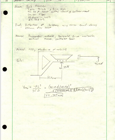
Analysis 10 was completed on the rear sub frame and the deflection it will have when the coil over applies the full force from the vertical drop test
Figure 2.10
Analysis 11: Steering Tie Rod Buckling

Continuing off of the steering bolt shearing analysis, the force that is transferred from that mount goes directly to the tie rod. Analysis 11 finds whether or not that force will cause the tie rod to buckle.
Figure 2.11
Analysis 12: Coil over Spring Rate

Analysis 12 finds the necessary spring rate that the coil overs need to be so that the coil over won't bottom out assuming that the drop test will be the most upward force that the coil overs will experience.
Figure 2.12