MET RC BAJA
Testing
The purpose of the testing is to see if the engineering designs and calculations in fact hold up to what is proved. Testing will be carried out in a manner that will be to the level of every requirement listed in the introduction. The reason the that the testing is only tested to the level needed is so that the car will be able to compete without sustain major damages. Each test performed will have the necessary measurements needed to prove that the requirements are met.
Most testing will only require simple measurements or data collection, but others will need to be more in depth by using calculations and observations. Requirement 1d.4 states that the car must be able to turn at full lock at a speed of 5 m/s without it rolling. This is a good example of a more in-depth test because the right speed needs to be calculated and execute to properly perform the test. Other testing will be done that specifically pertains to the ASME competition. One issue that occurred during the testing was the lack of data. More trials and testing parameters were added to give accurate and consistent data.
The cornering test was the first test to be completed in the spring quarter. To complete the test, the control was set to limit the speed so that each trial had accurate results. The speed was confirmed using a GPS strapped to the car. The test was completed on the southside of the Hogue Technology Building in the courtyard where the concrete was bare and flat. The test was performed and was able to meet the Requirement 1d.4 where the car must be able to take a turn with the steering at full lock at a speed of 5 m/s without rolling.
The second test deals with a vertical drop. The requirement states that the car must be able to withstand a 650 mm vertical drop without any broken or damaged parts. The test used 3 trials for each of the 3 heights that were 250 mm, 500 mm, and the required 650 mm. The test was successful with (Average) 50% suspension compression at 250 mm drop, 92 % for 500 mm, and 100 % at 650 mm. It also resulted in no damaged or broken parts.
The third test that will be displayed on the website is the frontal impact test. The requirement for this test states that the car must be able to handle a frontal impact to an individual wheel/tire without loss of steering control (2 degree change in steering angle from original alignment) at a rate of 2 m/s. This was completed by having 3 trials of driving the car into a blunt, perpendicular surface at 3 different speeds. This test was also successful and resulted in no broke or damaged parts and retained the full original steering test and did not exceed 2 degrees of steering change.
All other requirements were tested but had a pass/fail result. The requirements were the lower control arms must not deflect more than 7.62 mm with a 9.1 kg load place on the car, the suspension must have a minimum of 600 mm of travel, must be able to complete a U-turn in a 1 m radius, sustain traction with an immediate application of 75% throttle, a minimum of 35 mm of suspension articulation, coil overs must be less than 45% resting compression, and the steering must be within a 5-degree difference one direction to another.
.jpg)
In Figure 4.1, the setup for the cornering test is displayed. This test evaluated the center of gravity and the corner-ablity of the RC Baja car. The test was a success because the car was able to handle over 5 m/s in the corner with the steering being held at full lock.
Figure 4.1

Figure 4.2
To the left in Figure 4.2, displays how the speed was recorded in the trials. The speed on the GPS was used to base off what to limit the speed of the car. The transmitter has a speed limiting feature and so the exact speed can be set and be consistent for each trial for all the tests that are based off of certain speeds.

This video in Figure 4.3 is a speed trial at 6 m/s for the cornering test. As seen in the video, the car successfully completed the corner the first attempt but on the second attempt, it lost traction which is a fail. However, this speed exceeds the required maximum speed the car needed to complete. In result it is a pass.
Figure 4.3
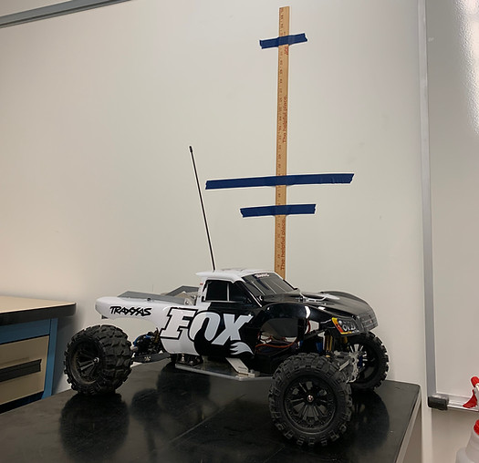
Figure 4.4 shows the set up for the vertical drop test. The measuring stick is attached to the wall with the set heights pre marked for ease and consistency of hitting the same drop height. The required drop height is 650 mm for the car. The test was completed in the senior project room on the second floor of Hogue Technology Building.
Figure 4.4

The video in figure 4.5 shows a trail of the vertical drop test. The test included 3 trials at 3 different heights. In the video, the drop is from a height of 650 mm which resulted in a successful drop with full compression of the suspension without any broken or damaged parts.
Figure 4.5

For the front impact test, a curb was used as the blunt, perpendicular object that the front tires would hit. This is shown in Figure 4.6. Although the curb in the image seems to be uneven, it is actually straight and perpendicular to the driving test where the tires make contact.
Figure 4.6

Figure 4.7 is a image taken from a frame on a slow motion video of the front impact test. It is hard to tell but the tires and suspension are deflecting slightly but the resulting, measured deflection of the steering was only 1.5 degrees which is still within the requirement.